 |
 |
|
| Restoring Lena-Contact-Sailing Home-Sailing Logs-Uphill photo Tour | ||
|
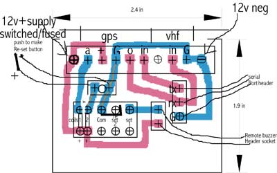
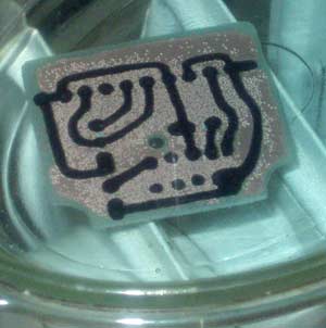
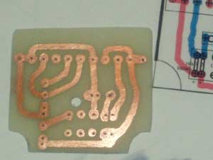
The circuit for the new Data Connection Box You would never believe how difficult it is to make up a little circuit like this - I found it so anyway. It looks so simple now - so if you want a little circuit for inter-connections for a box like this help yourself. Generally - etching the board was very easy. Just mark it out with an 'etch resist pen' on copper clad board - making sure it nice and clean and grease free beforehand. Then stick it in this etching fluid - took about 15 to 20 mins @ 40c - needs to be 'at least' 40c, no less, but not more than 50c. On the left - Circuit layout The Pcb Terminals at the top are 0.2" apart ( 2 x 0.1" hole centres ) Relay is a latching, twin coil, 2 A minature, direct pcb mounting, or into a 16 pin dil socket. The three others are pcb header plugs/sockets - spaced 2 pins apart for ease of circuit layout. The two relay coils are only spaced at 0.1" The vhf OUT is not connected - my Nasa does not have this - so top row you have - 12v+ supply in/ Gps-Alarm, 12v+, Ground, Nmea Out, Nnea In./Vhf - Nmea Out, Nmea In, Ground./ 12v NEG from bus. The Garmin A data wire supplies 12v neg for the remote alarm. This fires the primary coil - which then connects COM to SET ( sounding buzzer ) It then stays there - despite the Garmin supply switching off after about ten secs. So Buzzer stays on - until coil 2 is fired by the Re-set circuit, with a 'Push to make switch' on the end ( mounted near the Garmin display unit ) - this flips the connection back to COM and Re-set - Buzzer goes off. The relay has coil current of about 20 mA - so is well within the Garmin spec of 'under 100 mA' coil current. Left is the little circuit being etched.- then after about 20 mins - you just wipe off the resist pen ink with acetone. Worth giving the soldering points a bit of a rub up with something small and abrasive. You can get a special little abrasive pencil for this. Geoff - Feb 07 |
||