 |
 |
|
|
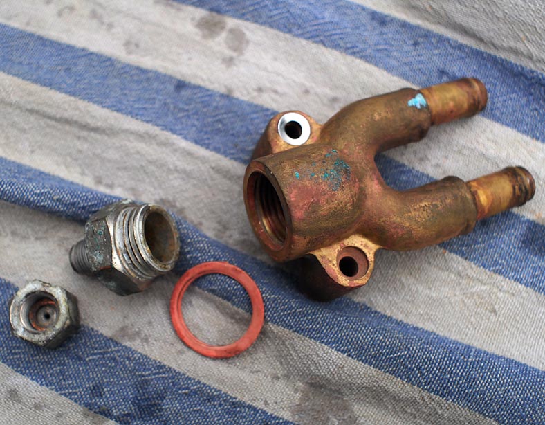
The Old Anti Syphon Valve - that didn't anti syphon ! An update on the engine work - 11th Jan 2014 Well - I'm sure it used to work ( see pic below ) - but it is to be fair the original thing as when I got the boat. I looked into these quite a bit - and there are some rip off prices for what is basically a rubber flap. One thing to bear in mind is it needs ideally to need very little pressure to break the seal. There is little weight of water in in a tube 1/2 ID about fifteen inches high - so simple things like a 15mm non return valve would be too stiff - they simply would not open and let in air. Hence the quoted 'best option' of having an actual small diam pipe running off the top open to the air and taking a small flow. There are a couple of issues here I wonder at. Firstly - with a swept u bend - and the top outlet as a restricted hole, and little resistence to the flow as it goes into the wet exhaust - and also it is being 'sucked' to some extent by the exhaust gas flow. So - I wonder ( without actually trying it ) whether any water would actually flow out of the top pipe ? - see the pic below. I shall try it I think - as an 'open' top to the upper loop is ideal and faultless ( unless it physically blocks off ) Secondly - and this is something I have never seen addressed, does the pump gain some 'help' from the exhaust 'sucking' water through the raw water hose run ? If you have an open upper loop - maybe this would affect the pumps ability ? Maybe not ? I see the old unit has a very small outlet hole through to the upper non return valve. ( not showing - but the main body has about a 3mm hole at the top of the loop - internally ) If the top then feeds overboard through a long length of small pipe, ( 6mm nylon seems ideal for this ) - I suppose this would restrict air flow quite a bit. My old anti-syphon valve. The body I shall be re-using. The top was a very small cap with a tight little rubber in it - which has perished and was stiff and non-fuctioning. Its dug out here
The old base unit is nice - and has a 1/2 bsp female fitting. So I have ordered from ASAP - a new non return, a lot chunkier than this one - about £10 or so, - plated brass and by Seaflow. | see here | This will screw into the 1/2 bsp on the old unit. It also has an extra outlet @ 3/8th bsp. I have a blanking plug for this - but it gives me the option to try an open pipe arrangement. If the main non-return seems fine, and responds to light release pressure I will go with that for now. But they can corrode up with salts, which can block the rubber flap etc. As I mentioned before - SSL dieselparts do a lot of nylon tube. I don't seem to see it too often in chandlers - maybe its there and I'm missing it ? My greaser line is 6mm nylon so have got new end fittings and sleeves for it while re- routing it. This would make an easy run to open hull - or an outlet into the aft cockpit. No problem coming off 3/8 bsp female to a comp fitting. So - if water does in fact flow out of a top tube when running ( unknown as yet ? ) - all I have to sort is a suitable exit fitting. I'm thinking a nylon 6mm could run down vertically from a through hull. or maybe a SS exit plate sikaflexed up - so the flow is into the cockpit sole just foward of the drains. I could see that - and it might be a useful sign I'm pumping water. But as I said - I'm not so sure water would actually make it out ? I would be happier with an open vent system. The New unit from ASAP I thought these units were vented on the top - through the typical small hole and rubber flap arrangement - not so - MUCH better. These are extremely nicely made ( chromed brass ) and have a simple rubber ball that sits on a machined conical seat. Flow in ( for air ) is on the side 3/8 bsp female port - this goes up to the top and then down to the lower 1/2 bsp mounting spigot. The ball drops in the top access plug and sits just above the 3/8 port. The ball is 15mm diameter - so airflow in is extremely good. This is so nice - so simple to open and clean - air flows in at the slightest pressure. So Brownie Points to Seaflow ! Looking down on the ball seating - that forms the restriction to outflow. A nice simple arrangement - and at £10, one of the nicest bits of marine hardware I've bought for years. The lower 1/2 bsp spigot screws into an existing loop - or could be teamed up with a simple 1/2 bsp T fitting plus hosetails. Seaflow also make similar cast loops with mounting plates - as my old unit. 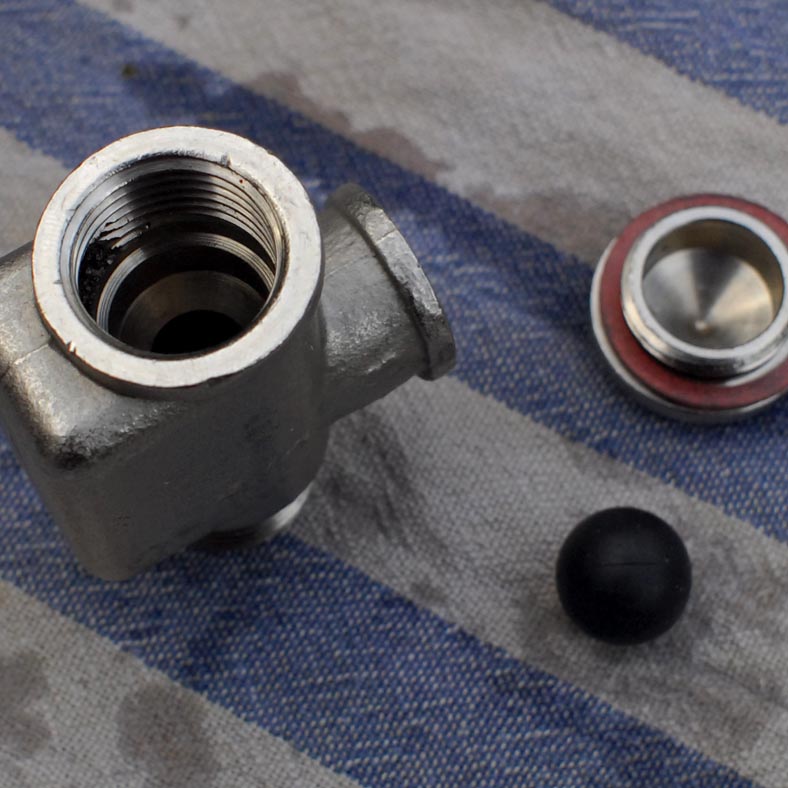 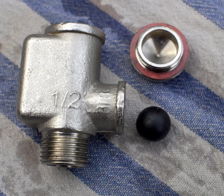
The ASAP - Seaflow Syphon break valve.
Since the outlet restriction is not a high pressure type seal - it will be interesting to see if any water makes it out of this 3/8 port. It can be fitted with a 3/8 bsp hosetail and some loop of 1/2 clear hose - to collect any small leakage. Of course the unit could also be used without the ball - and out of the side port to small pipework run overboard. Two cold days aboard ! - but managed to get the head back on and valve gear etc. I still have to re-install the tank and get the fuel lines all bled through - then I can check the timing maybe ? I still do not know about the compression - as the injector is out. I replaced the precombustion chamber and its packings loose, and the top heat washer. Easier to set valve gaps with no comp - and also the timing. I very carefully checked the block for flat. Throroughly cleaned - there was a worrying small mark which looked horribly like a small crack ! On very close inspection it seemed to be just a mark. Didn't seem to be a dig or scratch - and it was clear of the edge rim of the bore. Worried me for a bit ! The block was good for 0.02 mm everywhere - especially all around the bore edge. ( wear spec is 0.05mm ) So I was happy. Before you fit the head - you should torque the studs as specified. Two were very loose. In fact they all were loose - needing up to 1 1/2 full turns to get to 44 lt lbs. Not easy to torque these as you have to lock the nuts off together to at least 55 lbs or so, or they slip. I used spare M10 nuts rather than the head nuts. I carefully degreased both faces - white spirit, then Meths - then Acetone. Also cleaned degreased and brushed the stud threads. Cleaned the head blots and acertained which was the machined side to the washers - then sweetened them up flat on some fine wet and dry. Then oiled the nuts and washers. I then set the gasket - and the head assembly - then carefuly oiled the stud threads ( I didn't want any oil running down the studs onto the mating surfaces ) Assembled hand tight. I then torqued the bolts - in their correct sequence, in about five stages. 15 - 30 - 40 - 50 - 55 ft lbs. After about seven hrs or so - that evening - my gut reaction was to go around again at about 58 ft lbs. I could not have done this any more carefully ! One good thing is it went on in very cold conditions - and its going to be set for quite a while dry. I try to relax about these things - but I shall be a nervous wreck when I start it up ! Should be ok - !!! One thing of note - its not that easy to be sure the pushrods are sitting on the tappets right. Have a good practice with them before putting the head on - you can see more then. Once in - place you fingers on the tops and run through the four strokes - you can feel they are right then. You can feel where they slip in properly. Be careful with these as setting the rocker on them if out of their seats would not be good ! Also - if you do have the starter off - a good way to see tdc is with a torch shining at 90 deg to the flywheel. It casts a shadow onto the timing mark - from the cast V notch. Difficult to get your head in line to see it otherwise ! - and the V notch is some 20mm gap from the flywheel. While you are at it - make a paint mark on the crank pulley - maybe two in line to something on the Alt - to mark TDC. Better to replace the head with the injector out - no comp, so setting tdc easy. ( can't use de-compression lever with rocker cover off ! ) Geoff - Jan 2014 empty - table 0 0 space 6 - colour NO - main cell col 3, span 1 colour NO |
||