 |
 |
|
| Restoring Lena-Contact-Sailing Home-Sailing Logs-Uphill photo Tour | ||
|
With the cold, rain and wind - and dark so early/late I'm a little concerned that I've not been down to the boat for about a month. She should be ok - not too good for the batteries thtough.
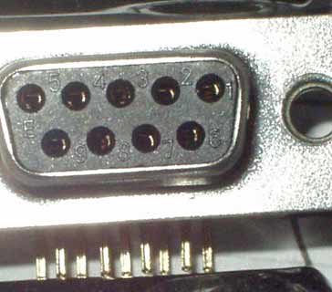
Hopefully this weekend looks promising - at least just to get down river at midday tide to check her out for a few hours - run engine. My backs been playing up all week - so can't do much except sit upright, or lay down, and I'm fed up with laying down - so have been trying to educate myself online with regard electronics. I am a complete Dumbo when it comes to electronics. I can solder, of sorts - and know enough to wire up basic 12v stuff and cable sizes etc - ie watts divided by volts = amps - but bring on 'diodes', 'resistors' and 'ohms' - and I'm lost ! The reason for this quest - was primarily that I wanted to install an external, loud buzzer, to the 152 Garmin gps - for anchor alarm mainly - something that would 'wake the dead'. Garmin provided the wire, Yellow on the data cable - but specified ' to the -ve of a relay, coil current less than 100mA. So what's all that about........? Also - I had been wondering what these 'diodes' were - for protecting solar panels draining current at night. I stumbled across the The Electronics Club - simply fantastic, for explanations of components - what they are/what they do. I can now work out what the amperage is - given a voltage and resistance ( ohms ). Useful - as many of the relays don't specify their coil current - only coil resistance in Ohms and voltage. http://www.kpsec.freeuk.com/index.htm There are various online descriptions of the nmea connections to wire up your own serial connection to a laptop from gps - you only ned three wires, G , in (RX) and out (TX ). These connectors are marked on the back, at least Maplins ones are - but you will need a strong magnifying glass to see them. So long as you can pick out even one numeral, you will be ok. ( I've found that Tesco reading glasses, 31/2 strength make great mag glasses ! - only about three quid) See link below for pic. If you buy a serial socket to wire up, generally a pc or laptop will have a 'male' at the back panel - ie 'it will be nine PINS ' - facing these pins, Pin 1 is top left. One bonus of all this imformation gathering - I've now come across things called 'PCB Terminal Blocks'. These are basically 'choc box' type connectors - usually in a row of three, which solder to a standard PCB stripboard - this is a board with loads of holes in at 0.1" centres - and strips of copper on one side, used for building circuit boards. These terminal blocks are tightened by a screw, but the wire contact surfaces are two flat plates - much superior to the average'choc box' direct grub screw, especially on small data wires. The fine data wires can be bared, bent double and tinned with solder. Going into this type of terminal also allows the wire to remain capable of feeding through small holes - or being removed easily through small holes. It means that when you want to connect up some data wires, all sort of going between one and another - gps, vhf , serial oulet - you can just get a little polycarb equipment box, and a small piece of stripboard ( Maplins etc ) - put on several rows of PCB terminals - so each wire has its own connector. ie GPS - one for 'ground', one for 'nmea out', one for 'nmea in', one for 'remote alarm' - and the same with the VHF and others. On the rear of the panel you make, or break the necessary connections. All the data 'grounds' would be linked by bridging the necessary copper strips, etc. GPS out, would link to VHF in, and to the required pin on a serial port etc. This makes a neat little arrangement where all wires can go to their own terminal - no box full of spaghetti ! While you are at it - put in a female serial outlet ( this will also fit down onto the board) you have a port for a serial cable if ever needed. Add the relay, and its protecting signal diode ( you see I'm learning fast about this stuff ) and you can give the Garmin 'yellow' alarm wire a terminal - then stick a DC chassis socket on and you can plug in your 110 dB pietso siren. ( I have now made my second attempt at an alarm box - see here ) A few relevent things I've learned. Serial connectors. Only three wires are used, on a laptop/pc serial connection to gps. Data IN ( Rx ) Data OUT ( Tx ) and ground ( --- 0v neg ) 1..2.. 3.. 4.. 5 Facing male Pins - 9 Holes, 5 at top, 4 below. ...6.7.8.9. Pin 2 = Rx ( recieve ) Pin 3 = Tx ( send ) Pin 5 = ground. You don't need to connect anything to the others. These are numbered on the plugs/sockets, but you will need your glasses ! - a bit clearer on the front of a female. - (see here for pic- some inginuity with a little Olympus 1.3 mpixel and a photo loupe ! ) The Nmea Out on the gps ( TX com 1 - Blue - on the garmin 152 ) connects to the Data IN on the Serial port ( Rx ) - and Nmea IN on the Gps ( Rx com 1 - Brown -Garmin 152 ) connects to the Data OUT ( Tx) on the serial port. Just think ( Rx - "Recieve" - Tx - "Transmit" ) - PC transmit to Gps receive. You can mount either male or female as a chassis socket. The no's stay the same - ie facing male pins, Pin 1 will be top right. These chassis plugs/sockets are only about 70 pence and are called D-Sub - Maplins etc. The no's are always the same - so long as you use serial cables. Ie - if you have a serial cable with male both ends - then facing the pins, both ends will have pin 1 Top Right - so it fits Pin 1 on the female. Beware the 'Null modem cable'. On a serial cable - Fem/Fem - Pinout 1 will be top right, on both ends, facing holes, to match the male pinout, - 1 top left. If in doubt, or to check your connections, use a multimeter on 'continuity' - as it does get confusing, especially when soldering from behind. What else have I learned.....well I started by wondering just which way the current was actually going - being that a solar panel, or for that matter, a battery charger - was actually putting current 'in' to the pos terminal.? Oh dear - Oh what a can of worms I opened for myself ! Suffice to say - 'Conventional current' flows from Pos + to Neg - ( in the circuit ) and Neg to Pos ( within the battery itself ) Actually, electronically, it is quite the reverse direction, with a Neg electrons 'sort of waveform' originating from Minus to Plus - but apparently it does not really matter which way it goes ! A diode is the equivalent of a tube with a flap valve in it. Its sybol looks like this Current can flow one way - Pos to Neg ( conventional ) Its probably better to think that essentially the voltage on the Annode side has to be 'greater' than on the Cathode, for the diode to become a conductor - and make the circuit. When Cathode is higher than Anode - its does not conduct at all. Really it is just a switch - responsive to the respective Voltages of either side. The difference needs to be about 0.7 V ( the inherent 'pressure' needed to 'open' the gate - hence Diodes of this type cause a 'voltage drop' of about 0.7 V ) Got that - not sure I have ! Small diodes, less than 1 amp are generally called 'signal diodes' - larger ones, ie over 1 amp. called 'rectifiers' or 'rectifier diodes' - essentially they are the same thing. So if searching in Maplins for 3 A diodes, best look under 'rectifiers' ! Schottsky type diodes cause less volt drop - as little as 0.2 V. You can apparently, solder a 3 amp recifier without worry - but a signal diode of 100mA probably is best to put a croc clip as heat sink between component and solder connection. So - on a solar panel, on the + wire - the diode will have its Annode to solar panel, Cathode ( black line ) to the 12 V Battery Pos terminal. When Annode voltage is greater than Cathode, battery will charge. Cathode side greater than Annode, ( night ) no current can flow. You can put it on the Neg wire - just put it the other way round. The panel I have just installed (see here) seemed to ahve a built in diode. The Sunware tech info didn't actually say it had - but I put a multimeter across it - and I get about 700 ohms one way and nowt the other. Also, rigged up off the boat, at home, I tried it with the Amp setting on the multimeter, in-line. Upside down on carpet - it pulled a reverse current of 2.5 mA - thats 25mA overnight, 175mA a week, about six weeks = 1 amp ! so not worried on that one. Maybe it does have a diode. Now, with regard my remote Alarm Maplins do sell 90 dB pietzo buzzers that only pull 10 mA - so I would think there is no reason why one should not go straight on to the dedicated data wire. ( this wire on the garmin 152 is just acting as the 'switched' neg feed for a 12v circuit to the relay - they just don't want it pulling more than 100mA . The Garmin 152 alarm is useless as it is - nearly inaudible, and only stays on for about ten seconds. I havn't tested it yet to see if the 0v yellow alarm wire stays constantly live while the alarm is sounding, or actually ocillates 'on/off' - as does the alarm sound. I've made my prototype data/alarm box with the relay made into a 'latching' circuit - where once activated, the alarm will sound until such time as you re-set it. The 107 Db buzer I've used ( loud ! ) will set to different tones - constant, two tone and pulsing. You can also get one at 90dB that plays a choice of ten American tunes - all for about three quid ! I needed it different to my engine alarm - but if it actually ocillates on/off from the 0v supply it won't make any difference with it latching. As soon as the relay's on, the Garmin wire will not have any effect on it. After a little more education on types of relays - I used a double coil latching relay. What happens here - is the primary coil flips the relay between COM and NO ( normally open ) , firing the buzzer - but it then stays there, regardless of the supply wire switching off again. To stop it, you press a Push to Make switch - which fires the secondary coil - which flips the relay back to connect CON and NC ( normally closed ) I etched the circuit myself, using Maplins copper clad board, their etch resistant pen ( which is really just a fine permanent marker ) then in their etching solution ( see here ) By the way - if you are building a manned rocket to the moon, and are making the trip yourself - don't trust the above info. I think its about right - but I wouldn't want your batteries to go flat shortly after arriving ! Bored......bad back........miserable weather..........just nearly set fire to chip pan......pouring red hot oil onto garden soil in rain..........in the dark !!!! Geoff - Nov 06/ Feb 07 |
||